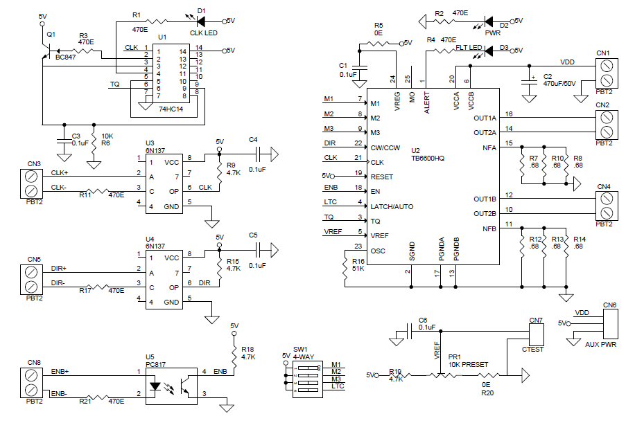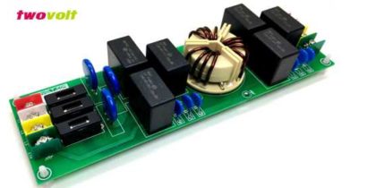
TB6600 Based 4.5A Bipolar Stepper Motor Driver
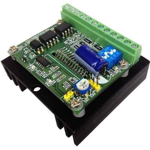
Bipolar stepper drive board described here has been designed around TB6600HG IC. The TB6600HG is PWM chopper type single chip bipolar sinusoidal micro-step stepping driver. Maximum Load 4.5A, Supply 10V to 42V DC.
Features
- Based on Single chip and Second chip for auto half current control
- Suitable for Nema17, Nema23, Nema34 bipolar stepper motors
- Suitable for 4Wires, 6 wires and 8 wires stepper motor.
- Forward and reverse rotations available
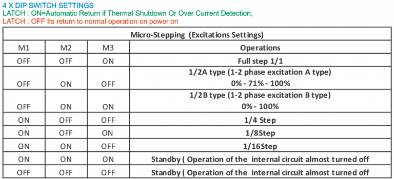
- Selectable Phase (Micro-step) drives 1/1, 1/2, 1/4, 1/8, and 1/16
- Maximum Input supply 42V DC Minimum Input supply 10V DC
- Output current 4.5Amps
- Output Fault Monitor LED indicator
- On Board Power LED indicator
- On Board step pulse input indicator
- Standby auto half current reduction circuitry onboard
- Built in Thermal shutdown (IC)
- Built in under voltage lock out (UVLO) circuit (IC)
- Built in over current detection (ISD) circuit (IC)
- Large capacitor to handle inrush current
Applications
- Robotics
- Large format Size Printers
- CNC
- Routers
- 3D Printers
- Machine Automations
- Camera Pan Tilt Heads
- Slot Machine
- Vending Machine
Heat-sink and Thermal Shutdown
The board has current sense resistors and these resistors has been set as per maximum load current 4.5A, If you use lower current motor, please set the PR1-Preset ( Potentiometer) to the required level for the motor. At maximum current load TB6600 IC will overheat in some time and a RED LED turns on. This LED goes off once the temperature falls to a safe operating level.
Micro Stepping
A 4way DIP switch is used to set the micro step modes (Full, Half, Eight, Sixteenth), please see the table for Micro step settings. DIP Switch settings should be changed when power is off so the correct selection is active at power up.
Step Pulse
Minimum positive duty cycle of the input step pulse should be 2.2us and required 5V (TTL) signal. A positive going pulse on the step input activates a step operation.
Current Settings
Average drive current can be set using a Preset (On Board PR1 Potentiometer). CN7 (CT) onboard connector is provided to measure the voltage to set the motor current (torque). Voltage range to set the torque 0.3V to 3.5V
Cautions
Never connect or remove supply wires, motor wires, or input interface when power is on, this can cause damage to drive.
Switch Off the Power to set the Micro stepping
Before using this drive, please have proper information about stepper motors, Motor impedance, Inductance and other specs.
Inputs
All Inputs are optically isolated to prevent the device for any kind of noise, short circuits.
Enable: Required 5V DC input, Set high Input disabled the drive, Set low input Enable the drive
Dir.: Required 5V DC input, Set high Input CW Rotation, Set low input CCW Rotation, Direction of the motor depends how stepper motor has been wired.
CLK: Step Pulse required 5V DC TTL pulse
Outputs
4 Wires, 6 Wires, 8 Wires Motors can be used with this drive in bipolar mode.On board LED for Alert
4XDIP SWITCH
SW4 (LATCH): ON=Automatic Return if Thermal Shutdown Or Over Current Detection OCCURS
SW4 (LATCH) : OFF= On Fault condition required power on/off