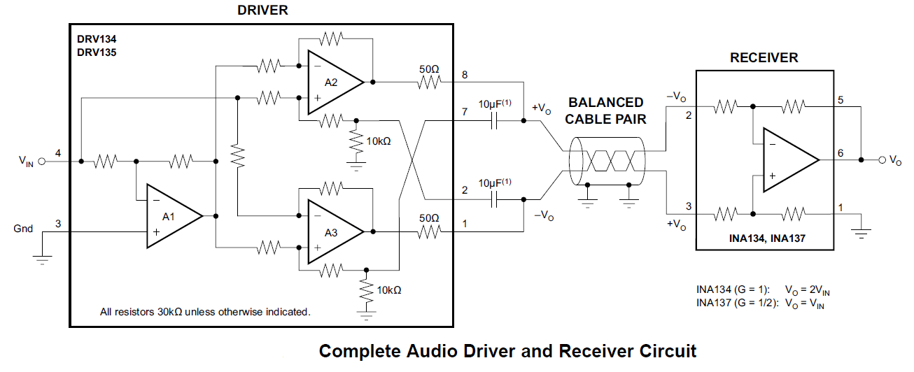
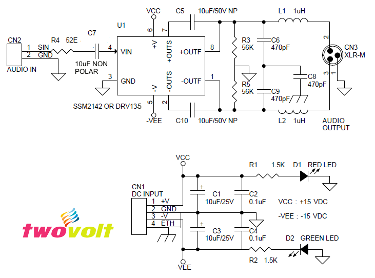
Balanced Audio Line Driver (Unbalance to Balance Audio Signal Converter) Using DRV135/SSM2142

The Mini board converts unbalance Audio signal into balance audio signal, the project is based on SSM2142 or DRV135 IC which are differential output amplifier that converts a single ended audio signal input to a balanced output pair. This balanced audio driver consists of high-performance op-amps with on-chip precision resistors. They are fully specified for high-performance audio applications and have excellent ac specifications, including low distortion (0.0005% at 1 kHz) and high slew rate (15 V/µs).
The on-chip resistors are laser-trimmed for accurate gain and optimum output common-mode rejection. Wide output voltage swing and high output drive capability allow use in a wide variety of demanding applications. They easily drive the large capacitive loads associated with long audio cables. Used in combination with the INA134 or INA137 differential receivers, they offer a complete solution for transmitting analogue audio signals without degradation.
Note: SSM2142 and DRV135 pin to pin compatible, any of this IC can be used.
Features
- Supply Dual 15V DC (+/-15V DC)
- Balanced Output
- Low Distortion: 0.0005% at f = 1 kHz
- Wide Output Swing: 17Vrms into 600 Ω
- High Capacitive Load Drive
- High Slew Rate: 15 V/µs
- Low Quiescent Current: ±5.2 mA IC
- Companion to Audio Differential Line Receivers
- Header Connector Provided for Audio Signal Input
- Header Connector for Supply Input
- Audio Output from XLR Connector
- Input Aux Audio Signal
- On-Board Power LED
Applications
- Audio Differential Line Drivers
- Audio Mix Consoles
- Distribution Amplifiers
- Graphic Equalizers
- Dynamic Range Processors
- Digital Effects Processors
- Hi-Fi Audio Equipment’s
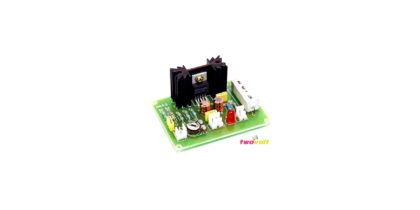
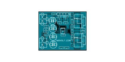
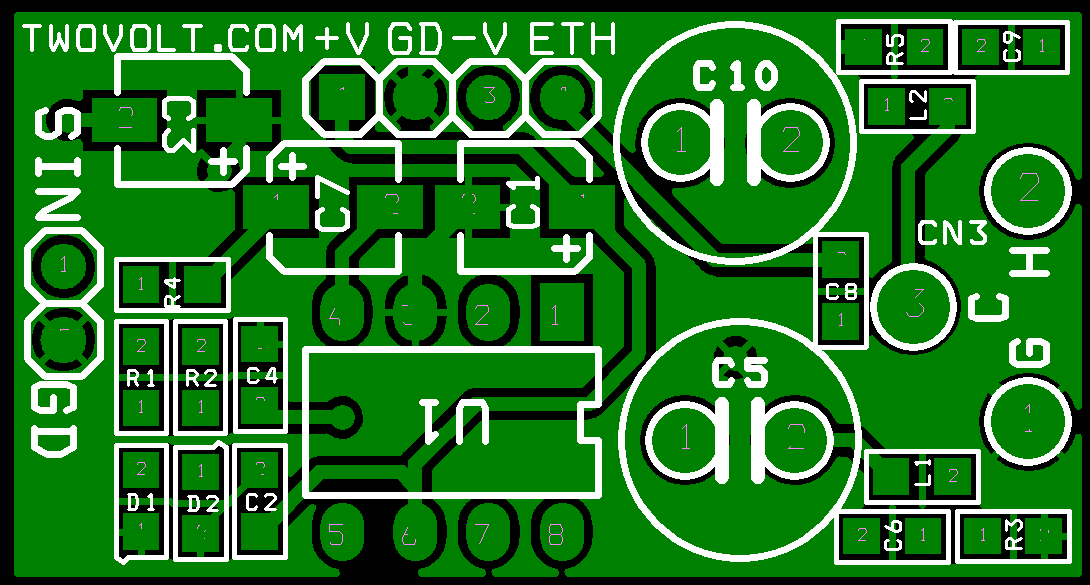
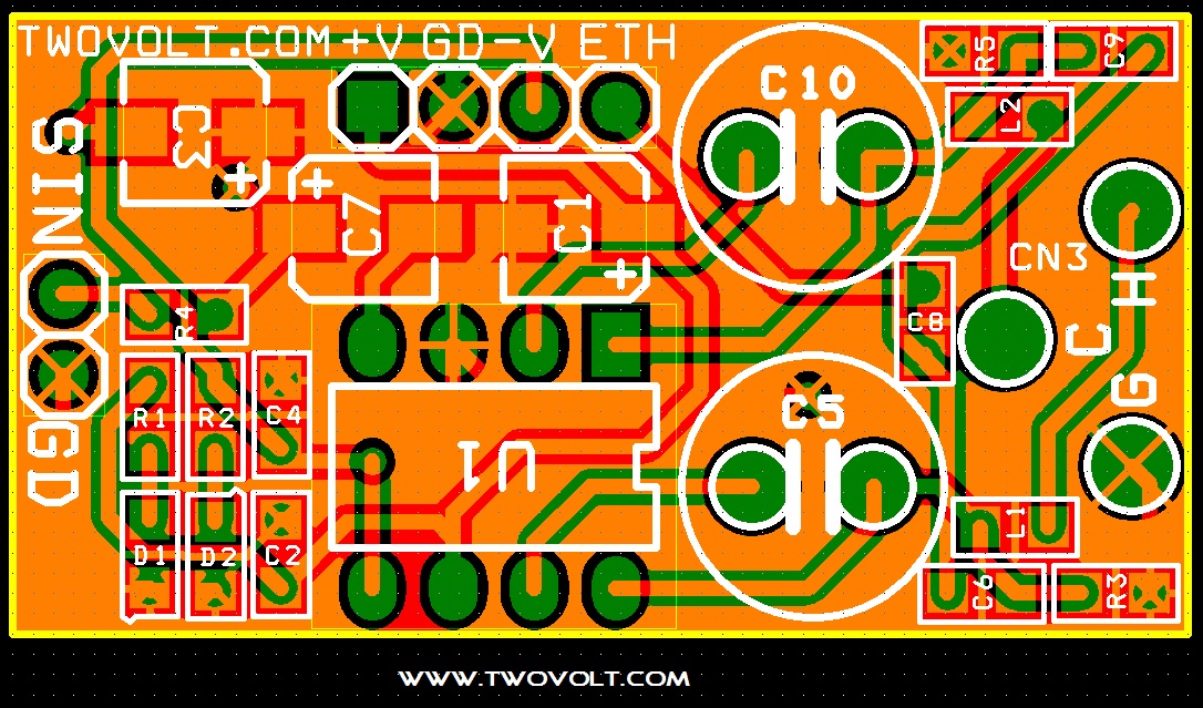
Components
- Capacitor C5, C10, C7 Non-Polar Capacitors
- All Resistors SMD 0805 5%
- LED SMD 0805
- C1,C3,C7 Electrolytic Capacitors SMD
- Output XLR Male Connector
- ETH Chassis Ground
Design Requirement
Consider a design with the goal of deferentially transmitting a single ended signal of up to 22.2 dBu through 500 ft of cable with no load at the receiving side. The signal at the end of the cable should have no more than 0.002 per cent of total harmonic distortion plus noise (THD+N) at 10 kHz and less than 0.0005 percent of THD+N for frequencies between 20 Hz and 1 kHz.
The system is required to put out a single-ended signal 0 dB with respect to the input signal and accommodate inputs with a peak to RMS ratios of up to 1.5 for the maximum 22.2 dBu range established above.
The DRV134 and DRV135 were designed for enhanced ac performance. Very low distortion, low noise, and wide bandwidth provide superior performance in high-quality audio applications. Laser-trimmed matched resistors provide optimum output common-mode rejection (typically 68dB), especially when compared to circuits implemented with op-amps and discrete precision resistors. In addition, high slew rate (15 V/μs) and fast settling time (2.5 μs to 0.01%) ensure an excellent dynamic response. The DRV134 and DRV135 have excellent distortion characteristics. As shown in the distortion data provided in
the Typical Characteristics section, THD+Noise is below 0.003% throughout the audio frequency range under various output conditions. Both differential and single-ended modes of operation are shown. In addition, the optional 10μF blocking capacitors used to minimize VOCM errors have virtually no effect on performance. Measurements were taken with an Audio Precision System One (with the internal 80 kHz noise filter
Example Circuit With Balanced Line Receiver