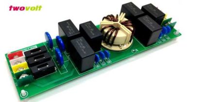
4Amps Bipolar Micro-Stepper Driver Using LV8727
The Project is based on LV8727E IC from ON Semiconductor. The LV8727 is a PWM current-controlled micro step bipolar stepping motor driver. This driver can provide eight ways of micro step resolution of 1/2, 1/8, 1/16, 1/32, 1/64, 1/128, 1/10, 1/20, and can drive simply by the step input. This Bipolar Driver works with supply input 9V to 36V (Replace L317 with L317HVT for supply input up to 45V DC). Load current up to 4Amps.

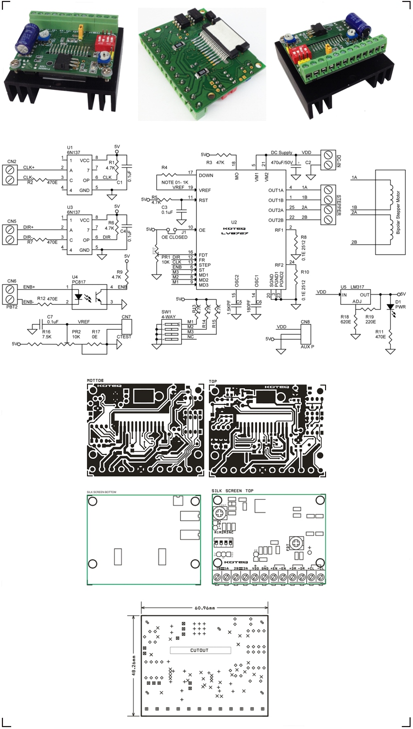
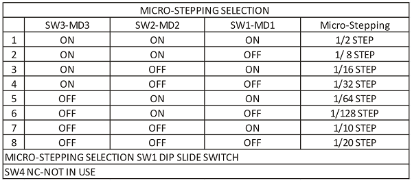
4 Amps Bipolar Stepper Motor Driver Using LV8727 Schematic, PCB Layout
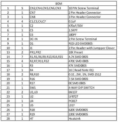
Micro-Step Setting
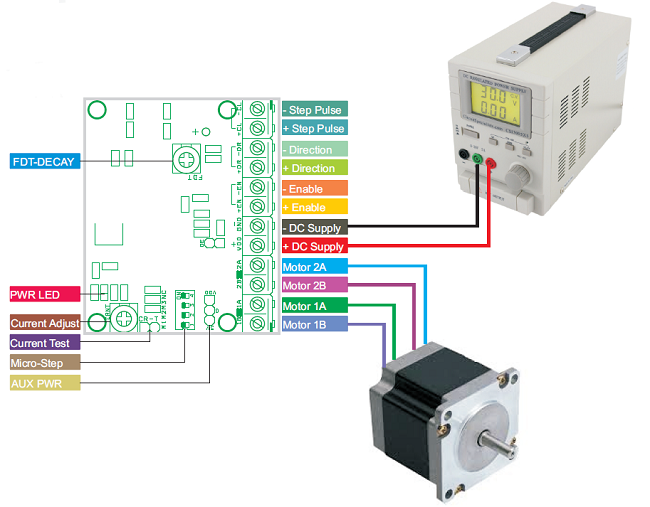
4 Amps Bipolar Stepper Motor Driver Using LV8727 BOM
Features
- Supply 9V to 36V DC (Replace L317 with L317HVT for Supply up to 45VDC)
- Load Current Up to 4Amps
- Inputs: Step Pulse, Direction, Enable
- Micro-Stepping: 4 Way DIP Slide Switch
- On Board Power Indication
- On Board L317 for 5V DC Regulator
- Current Adjust Preset
- Over Current protection
- Thermal Shutdown
- FDT Adjust Preset (DECAY Setting)
- Single-Channel PWM current control stepping motor driver.
- Output Current 4Amps
- Micro Stepping 1/2,1/8,1/16,1/32,1/64,1/128,1/10,1/20 Step are selectable.
- Advance the excitation step with the only step signal input
Output Current Settings (PR2 Preset Constant Current Setting )
- Current Output= (VREF/3)/0.1E (Shunt Resistor R8, R10)
- Example: (VREF 0.9V/3)/)0.1E=3Amps
Enable (Stand-by function)
When enable input is high the ST pin is at low levels, The IC enters stand-by mode, all logic is reset and output in turned off
Keep Enable input low (No Signal Input at Enable) for Normal operations, Apply 5V at disable the drive
Jumper-J1 Output Enable ( J1 Closed for Normal Operation)
Jumper Open put the output forced off and goes to high impedance. However the internal logic circuits are operating, so excitation position proceeds when the STP is input, when J1 close, the output level conforms to the excitation position proceed by the step input.
FDT DECAY mode setting (PR1-Prest)
Current DECAY method is selectable as shown below by applied voltage to the FDT pin.
3.5V to 5V Slow DECAY
3.1V to 3.5V Inhibited Zone
1.1V to 3.1V or Open Mixed DECAY
0.8V to 1.1V Inhibited Zone
0 to 0.8V Fast DECAY
Note: It is not recommended e to change DECAY method during Motor operation.
Note 01 DOWN output Pin
This pin is turned ON when no rising edge STEP between the input signals. This pin used to set the holding current when motor at HOLD state. Its help reducing the current when motor is not moving and it’s in Holding position.
R4 is associated to control the holding current when motor is in HOLD State, value of R4 to be calculated as per Input Ref voltage, and required holding current, see below formula to calculate the R4
Down Output OFF: VREF=5VXR2/(R1+R2)=0.741V
Down Output On: VREF=5VXR2 (R2IIR4)/(R1+(R2IIR4)=0.126V
Note02 R1 and R2 Divide PR2 and R4=1K
CN8 : 3Pin Header Connector
Auxiliary Power output 5V DC, GND, VDD-Supply Voltage
CN7 : 2 Pin Header Connector
Current Test (Voltage)
4 Amps Bipolar Stepper Motor Driver Using LV8727 Connections