10 Events Programmable Timer Using DS1307 RTC and PIC16F72
This project is a 10 Event Programmable Timer Using DS1307 RTC with its own battery backup. This kit can find many uses around your house, office or workshop to turn on, trigger or just sound a alarm at any given time.

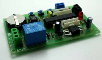
![]()
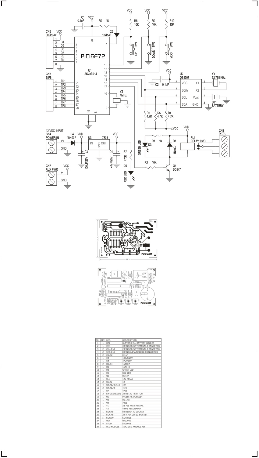
10 EVENT PROGRAMMABLE TIMER SCHEMATIC, PCB, BOM
A total of up to 10 alarms can be programmed with this kit. On board relay RL1 comes on for 4 seconds when the alarm time is reached. We also get a trigger pulse on one of the alarm pins set on Connector CN5. CN5 has 8 alarm pins which can be used to trigger external hardware of your choice, corresponding to Alarm Numbers shown on the LCD. A logic level of 0 and 5V @ 20mA DC is available on these pins and care should be taken not to drain any more power from these pins. It’s advised to use some buffer or isolating circuit in between this kit and the driving board to prevent spikes and excess drain of current from these pins. You could use any of our kits from the “Building Blocks” category for interfacing this kit with the external world.
A bright dual line LCD displays all the required information to you and also provides a very simple way to program this Programmable timer. This timer is programmed using 3 tactile switches available on the PCB.
The circuit comfortably runs on DC power of 12 V @ 300mA connected at CN4 Marked on the Overlay. The Polarity is also clearly marked on the PCB. A reverse polarity diode (D4) prevents damage to the Circuit in case of reverse polarity connection. On proper connection of the DC supply the PWR On Indicator LED (D5) must glow, indicating all’s OK. U3 is the Voltage regulator IC which provides a constant and regulated supply to the Board. SW1, SW2 and SW3 are the main control switches used for initial configuration and alarm setting of the circuit. CN7 (AUX PWR) connector provides regulated 5V DC for external devices connected to this board. Care must be taken to take supply from this point as it is routed through U3 IC which is rated at 1A peak current. This circuit has an onboard battery backup for the RTC (Real Time Clock) used, which means the Clock keeps running even if the main supply to the board is removed.
Configuring the Programmable Timer:
- This present code supports 10 Alarm setting within 24 hours and can select from a range of 8 triggers available at Connector CN5.
- At start up the LCD displays 5 preprogrammed alarm setting, before it enter the service phase. The service phase refers to the stage where the circuit constantly keeps checking the alarm set time with the RTC time.
- Hours consideration is 24 Hour format.
- The last alarm executed is stored in a non volatile memory, so that when ever power fails to the board, the clock resumes from the same alarm number which was being compared / services. A problem can arise if the power comes back after the alarm set time has been crossed. In which case you may either need to reconfigure the circuit on reset the RTC Time so that the particular alarm is crossed and a new alarm time is advanced.
- The Alarms/RTC can simply be set by pressing the MOD Switch (SW3) This is followed by a message on the LCD screen which ask you if you want to set the RTC Time or Alarm Time. Pressing the UP Switch (SW1) at this point take you to the RTC set menu and pressing the DOWN switch (SW2) takes you directly to the Alarm set function.
- Setting Alarm: Press the DOWN switch (SW2) to enter the alarm set routine. This routine starts with the LCD display showing the current alarm number which is being serviced / monitored. So if it was monitoring Alarm # 5, it would start from Alarm #5 and show you currently stored values for this alarm number. To edit you would first need to set the Alarm Hour, then Alarm Minute, then the Trigger number on CN5 connector. You can skip each of the item to the next configuration by pressing the MOD key once. For example if you only want to change the Alarm Pin number for Alarm #5 which presently triggers #3 to #7 then press MOD switch twice to skip entering Alarm Hour and Alarm Min to reach this option. This is the last option setting for any of the alarm stored. After you press the respective switches to arrive at your choice, press the mode switch to confirm. A confirmation message is shown on the LCD screen which says “PRESS SET 2 WRIT”. If you want to write / store this information into the chip then press the mode switch once and you enter the next alarm number. This procedure has to be repeated for each of the alarms you want to configure. The only way out of this configuration menu / setup is to press either of the other two switches, UP or DOWN when the confirmation message “PRESS SET 2 WRIT” is flashed on the LCD. When you press either of the switches the information does not get written into the IC and is unchanged for that particular alarm setting. The clock resumes from the last alarm number that it was monitoring / serving.
- Setting the RTC Time is straight forward. Just keep changing the value, by pressing the UP/DOWN key and moving on with the MOD key.
- The LCD display shows – On the top line Set : Alarm Hours: Alarm Min – Trigger pin # / Alarm Number; on the lower line : Time: RTC Hour: RTC Min: RTC seconds.