TEMPERATURE READER USING LM35 SENSOR & PIC16F676 SCHEMATIC
| Supply Voltage : | 7 ~ 9 V DC |
| Difficulty Level : | Simple |
| Dimensions : | |
| I/O Voltage : | 5 VDC |
| Jumpers | 2 |

This is a simple circuit to measure the temperature of any environment and display it on a 16×2 LCD module (C013). This is just an temperature indicator project and not a controller circuit.
The circuit uses a PIC16F676 Microcontroller to read a LM35 Temperature sensor and display the results on the LCD. The onboard ADC on the microcontroller converts the analog signal from the LM35 sensor, computes the results and displays it on the LCD.
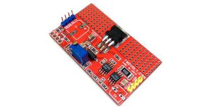
- Preset PR1 allows the user to adjust the ADC Reference voltage for the project.
- Temperature sensor (LM35) is connected by a relimate connector at CN3 connector.
- U3 is a voltage regulator IC, 7805 which provides a regulated voltage to the entire circuit.
- D2 is a reverse polarity protection diode to prevent against wrong polarity connection of DC supply at connector CN1.
- LCD Module – C013 is connected at connector marked U1. Please solder corresponding pins marked on this PCB with the One marked on the PCB.
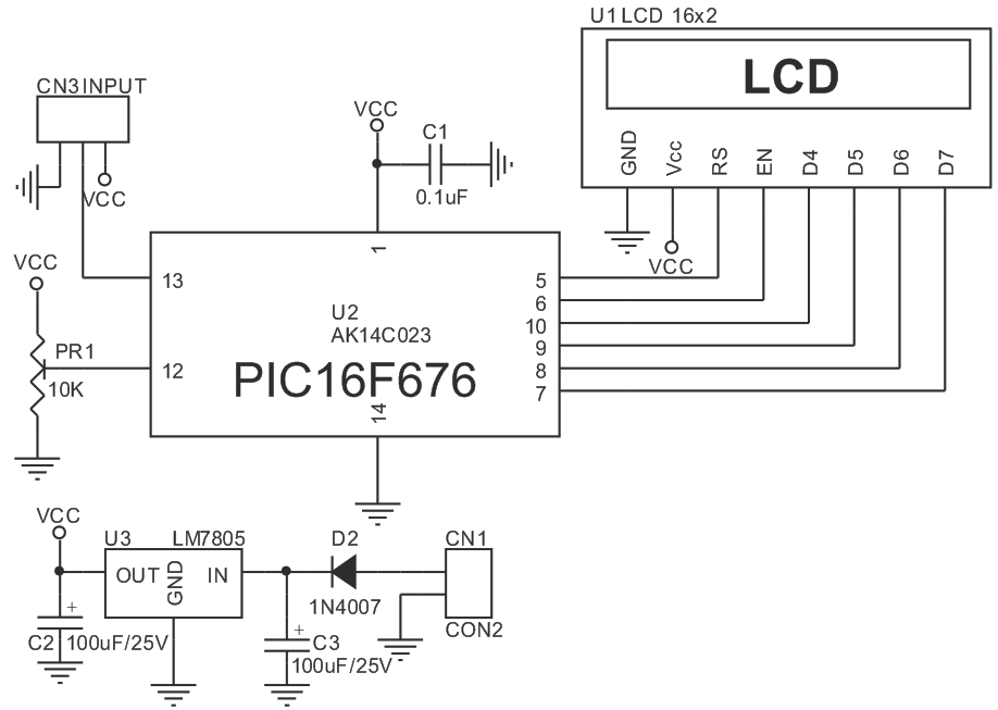
TEMPERATURE READER USING LM35 SENSOR AND PIC16F676 CIRCUIT
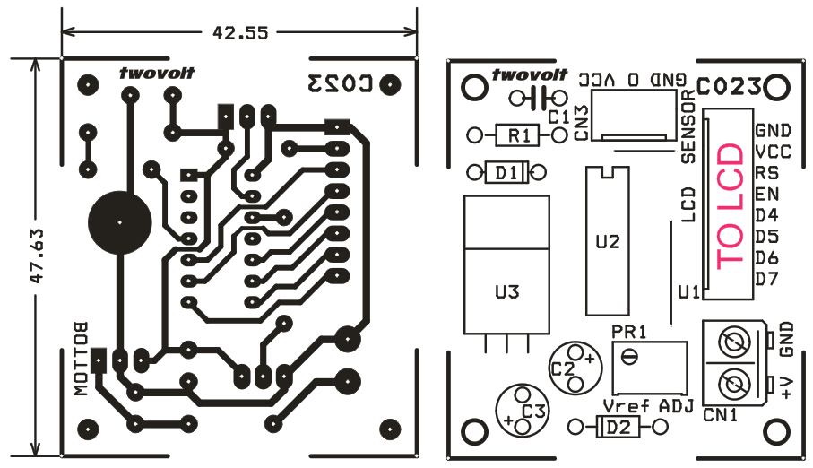
TEMPERATURE READER USING LM35 SENSOR AND PIC16F676 PCB LAYOUT
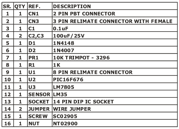
TEMPERATURE READER USING LM35 SENSOR AND PIC16F676 BOM
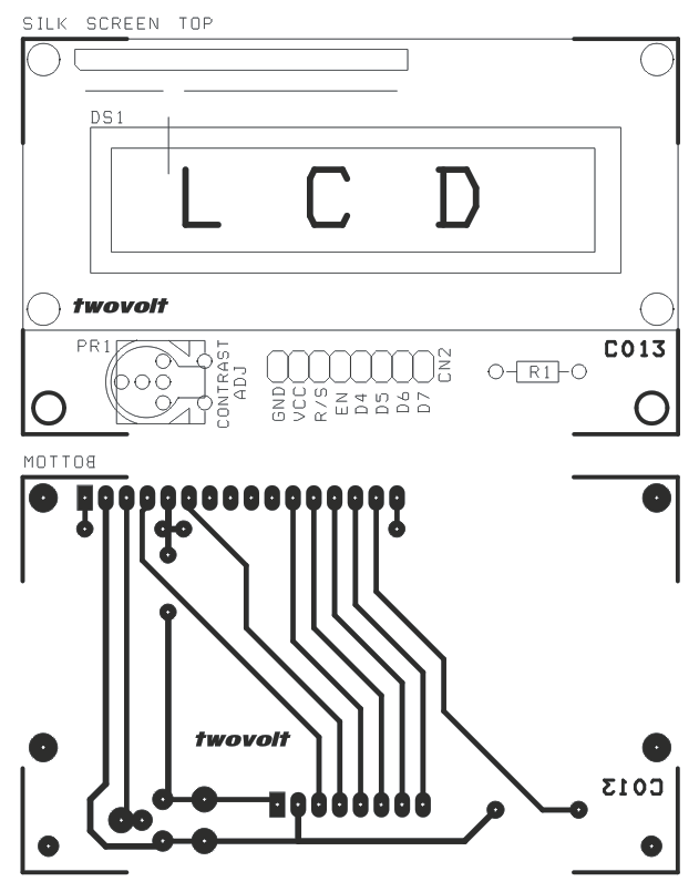
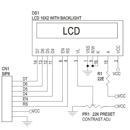
LCD CIRCUIT