5V To 12V Step Up DC-DC Converter Using LM2577
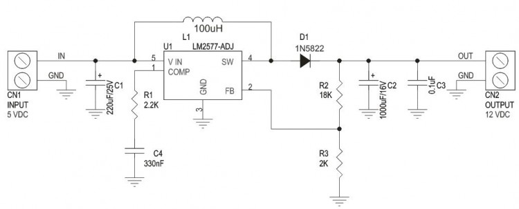
Step up DC-DC converter is based on LM2577-ADJ IC, this project provides 12V output using 5V input, maximum output load 800mA. The LM2577 are monolithic integrated circuits that provide all of the power and control functions for step-up (boost), fly back, and forward converter switching regulators. The device is available in three different output voltage versions: 12V, 15V, and adjustable.
![]()
Requiring a minimum number of external components, these regulators are cost effective, and simple to use. Listed in this data sheet are a family of standard inductors and fly back transformers designed to work with these switching regulators. Included on the chip is a 3.0A NPN switch and its associated protection circuitry, consisting of current and thermal limiting, and under voltage lockout. Other features include a 52 kHz fixed-frequency oscillator that requires no external components, a soft start mode to reduce in-rush current during start-up, and current mode control for improved rejection of input voltage and output load transients.

Features
- Requires Few External Components
- Input 5V DC
- Output 12V DC
- Output Load 800mA
- Current-mode Operation for Improved Transient Response, Line Regulation, and Current Limit
- 52 kHz Internal Oscillator
- Soft-start Function Reduces In-rush Current During Start-up
- Output Switch Protected by Current Limit, Under-voltage Lockout, and Thermal Shutdown
Project is based on LM2577-ADJ IC for flexibility to obtain other output voltages by changing value of feedback resistors R2 and R3
Output Voltage Formula V Out=1.23V (1+R2/R3) (Read Data Sheet for more information about Inductor value, Capacitor, Feedback resistors, Output current and voltage)
How It Works
LM2577 turns its output on and off at a frequency of 52 KHz, and this creates energy in the inductor L1.
When the NPN switch turns on, the inductor current charges up at a rate of vin/L1, storing current in the inductor. When the switch turns off,, the lower end of the inductor flies above Vin, discharging its current through diode into the output capacitor at rate of (Vout-Vin)/L1. Thus energy stored in the inductor during the switch on time is transferred to the output during the switch off time. The output voltage is controlled by amount of energy transferred which , in turn, is controlled by modulating the peak inductor current. This is done by feeding back portion of the output voltage to the error amp, which amplifies the difference between the feedback voltage and a 1.23V reference. The error amp output voltage is compared to a voltage proportional to the switch current ( ie., inductor current during the switch on time)
The comparator terminates the switch on time when the two voltages are equal, thereby controlling the peak switch current to maintain a constant output voltage.