65W Laptop Power Adapter Circuit Diagram

The schematic in Figure 1 depicts a notebook adapter power supply employing the Power Integrations® TOPSwitch®-HX TOP258EN off-line switcher in a fl yback configuration. This power supply operates from a universal input to provide a 19 V, 65 output capable of operation in a sealed enclosure at an ambient temperature of up to 40 °C. The TOP258EN (U1) has an integrated 700 V MOSFET and a multi-mode controller to regulate output by adjusting the MOSFET duty cycles, in response to current fed into the Control (C) pin. The Eco Smart® function in U1 provides constant efficiency over an entire load range. Using a proprietary multi-cycle-modulation (MCM) function eliminates the need for special operating modes triggered at specific loads and operating conditions, optimizing performance for existing and emerging energy-efficiency regulations. Fuse F1 provides protection to the rest of the circuit from catastrophic failures. Common-mode inductors L3 and L4 provide line fi ltering. X-capacitor C1 provides differential fi ltering, and resistors R1 and R2 provide safety from shock upon AC removal. Bridge rectifi er D1 rectifies the AC input, and bulk capacitor C2 fi lters the DC. Y-capacitor C11, connected between the transformer (T1) primary and secondary side provides common-mode filtering.
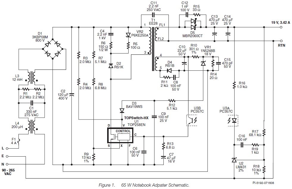
Circuit From www.powerint.com