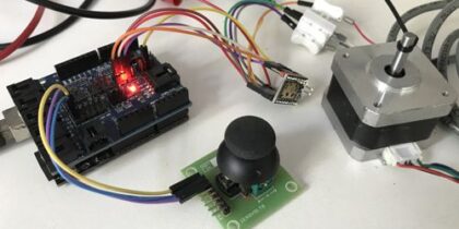
Arduino PID Brushed DC Servo Motor Position Control Using Joystick
Thanks raydike for the code, Motor has 1000 Lines Encoder motor moves half rotation following joystick, its takes approx 900mA current with 12V DC input.
Features
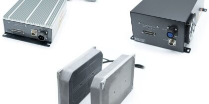
- Supply 12V-24V DC L298 For Motor
- Arduino UNO
- Motor Movement Half Rotation
- Encoder 1000 Lines
- Encoder with Incremental A and B Channel
- DC Motor 24V DC Brushed Type
- Gear Harmonic Drive 50:1
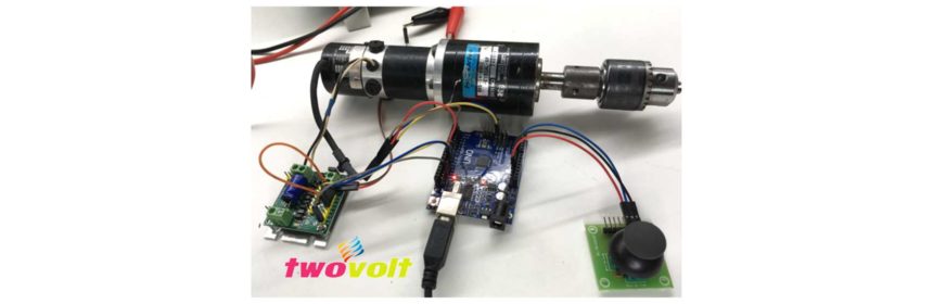
Arduino Pins
- D2 Encoder Channel A
- D8 Encoder Channel B
- D9 I1 L298 Board
- D10 I2 L298 Board
- A0 Analog pin Joystick
Note : If you are using twovolt L298 board Connect I1 to D9 of Arduino, I2 D10 of Arduino, E1 need s to be hook up with 5V DC available on L298 board. L298 board provided with 5V regulator , in case of Arduino UNO need s 5V power.
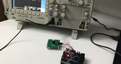
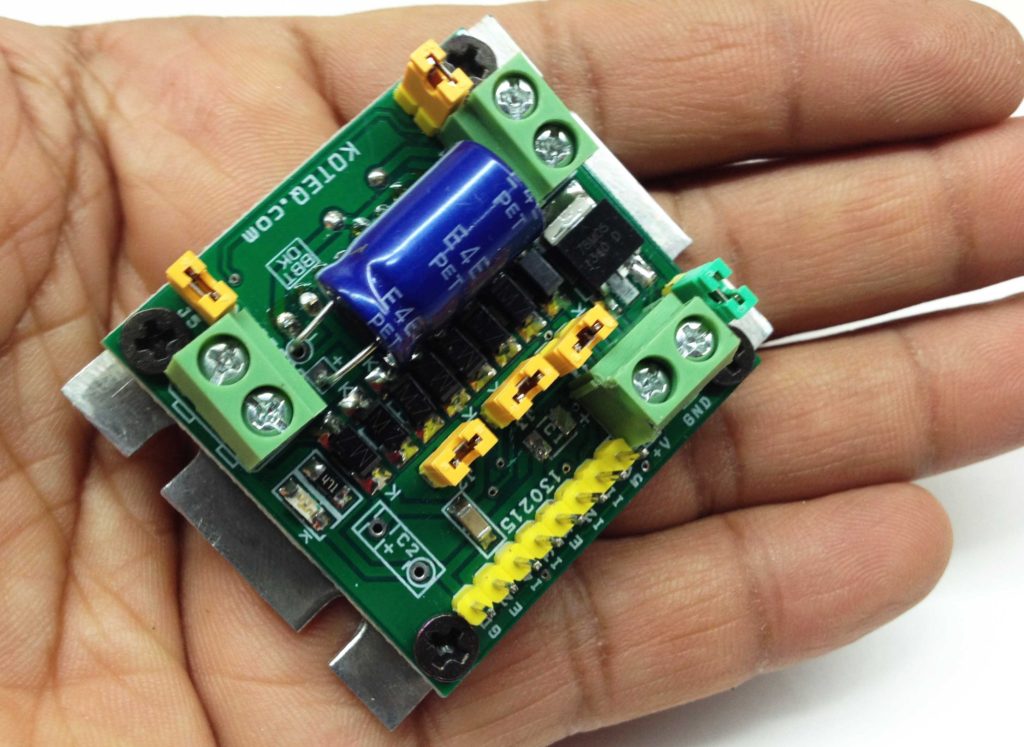
L298 Board Schematic and PCB Layout
Arduino Code : Original Author Of The code raydike
// PID motor position control.
// Thanks to Brett Beauregard for his nice PID library http://brettbeauregard.com/blog/2011/04/improving-the-beginners-pid-introduction/
#include <PinChangeInt.h>
#include <PID_v1.h>
#define encodPinA1 2 // Quadrature encoder A pin
#define encodPinB1 8 // Quadrature encoder B pin
#define M1 9 // PWM outputs to L298N H-Bridge motor driver module
#define M2 10
double kp = 1 , ki = 50 , kd = 0.01; // modify for optimal performance
double input = 0, output = 0, setpoint = 0;
long temp;
volatile long encoderPos = 0;
PID myPID(&input, &output, &setpoint, kp, ki, kd, DIRECT); // if motor will only run at full speed try ‘REVERSE’ instead of ‘DIRECT’
void setup() {
pinMode(encodPinA1, INPUT_PULLUP); // quadrature encoder input A
pinMode(encodPinB1, INPUT_PULLUP); // quadrature encoder input B
attachInterrupt(0, encoder, FALLING); // update encoder position
TCCR1B = TCCR1B & 0b11111000 | 1; // set 31KHz PWM to prevent motor noise
myPID.SetMode(AUTOMATIC);
myPID.SetSampleTime(1);
myPID.SetOutputLimits(-255, 255);
Serial.begin (115200); // for debugging
}
void loop() {
setpoint = analogRead(0) *25; // modify to fit motor and encoder characteristics, potmeter connected to A0
input = encoderPos ; // data from encoder
// Serial.println(encoderPos); // monitor motor position
myPID.Compute(); // calculate new output
pwmOut(output); // drive L298N H-Bridge module
}
void pwmOut(int out) { // to H-Bridge board
if (out > 0) {
analogWrite(M1, out); // drive motor CW
analogWrite(M2, 0);
}
else {
analogWrite(M1, 0);
analogWrite(M2, abs(out)); // drive motor CCW
}
}
void encoder() { // pulse and direction, direct port reading to save cycles
if (PINB & 0b00000001) encoderPos++; // if(digitalRead(encodPinB1)==HIGH) count ++;
else encoderPos–; // if(digitalRead(encodPinB1)==LOW) count –;
}