
New
12V 10Ah and 6V SLA, Lead Acid Battery Charger Circuit Using BQ24450 IC
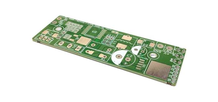
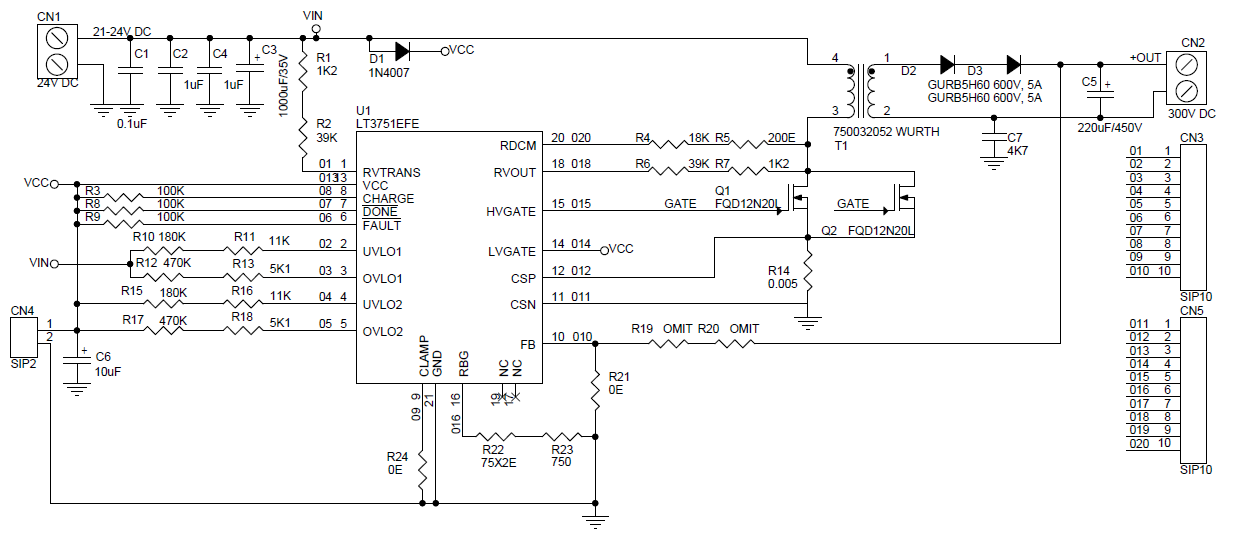
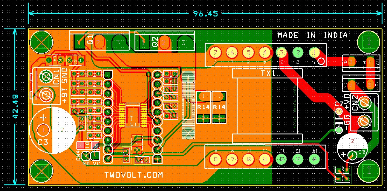
High Voltage Capacitor Charger Input 21-24V Dc and Output 500V DC
Difference Amplifier Forms Heart of Precision Current Source
Precision current sources provide a constant current in many applications, including industrial process control, instrumentation, medical equipment, and consumer products. For example, current sources are used to provide excitation for resistance-temperature detectors (RTDs) in process-control systems; to measure unknown resistors, capacitors, and diodes in digital multimeters; and to drive 4 mA to 20 mA current loops, which are widely used to transmit information over long distances.
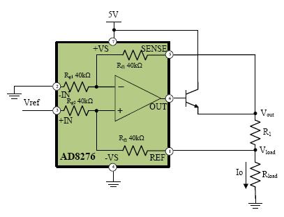
Precision current sources have traditionally been built using op amps, resistors, and other discrete components—with limitations due to size, accuracy, and temperature drift. Now, high-precision, low-power, low-cost integrated difference amplifiers, such as the AD8276, can be used to achieve smaller, higher performance current sources, as shown in Figure 1. The feedback buffer uses amplifiers with low offset and low bias current, such as the AD8538, AD8603, AD8605, AD8628, AD8655, AD8661, AD8663, OP177, or OP1177, depending on the required current range.

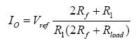
The output current can be calculated as follows:
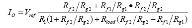
If Rg1 = Rg2 = Rf1 = Rf2, the equation can be reduced to:

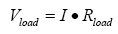
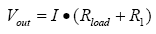
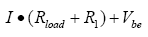
The maximum output current is limited by the op amp input range, diff amp output range, and diff amp SENSE pin voltage range. The following three conditions must be met:
 |
within op amp input range |
 |
within SENSE pin voltage range = 2×(–Vs) – 0.2 V to 2×(+Vs) – 3 V |
 |
within AD8276 output voltage range = –Vs + 0.2 V to +Vs – 0.2 V |
The SENSE pin can tolerate voltages almost twice as large as the supplies, so the second limitation will be very loose. The wide 2.5-V to 36-V supply range makes AD8276 ideal for many applications. The maximum gain error of A- and B-grades is 0.05% and 0.02%, respectively, allowing current sources with up to 0.02% accuracy to be achieved.
Configuration Variations
For cost-sensitive applications that can tolerate a little more error, the circuit can be simplified by removing the feedback buffer, as shown in Figure 2.
With
the output current is:
For

If the required output current is less than 15 mA—the output capability of AD8276—then the boost transistor can be eliminated, as shown in Figure 3. If both low current and reduced accuracy are acceptable, the simpler, lower-cost configuration of Figure 4 can be employed.