LOAD CELL FORCE SENSOR INSTRUMENTATION AMPLIFIER -analog output

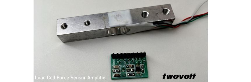
Here is my newly developed Load Cell amplifier circuit. Circuit provides very accurate reading. I have tested this circuit with 5Kg Load Sensor. Output is almost 0 to 5V / 0 to 5Kg. Circuit is based on INA326 Instrumentational Amplifier. Gain is set 500, circuit works with 5V DC input. The INA326 is  high-performance, low-cost, precision instrumentation amplifiers with rail-to-rail

Read more

0.5A to 4AMPS VOLTAGE CONTROLLED CURRENT SOURCE

This is very accurate voltage to current source, can be used in many applications such as LED drivers, TEC drivers, Power Supply, Battery charger. Download PDF Document Download PDF Schematic Download LT1789-1 Data Sheet Download LT1636 Data Sheet Supply Input 3.3V to 32VI-LOAD=VIN/RSENSEX10=1A PER VOLTRISE TIME 250us, 10% TO 90%1A TO 2A OUTPUT STEP INTO 0.25 OHMS LOAD   FORMULA

Read more

Rail to Rail Out Instrumentation Amplifier INA333 MODULE for Arduino

This module is Low-Power, Zero-Drift, Precision Instrumentation Amplifier, This module can be use in many applications like Bridge Amplifier, ECG Amplifiers, Pressure Sensor, Medical Instrumentation, Weigh Scales, Thermocouple Amplifier, RTD Sensor Amplifier.  Supply range 1.8V to 5.5V DC, easy Arduino interface.     The INA333 device is a low-power, precision instrumentation amplifier offering excellent accuracy. The versatile 3-operational amplifier design,

Read more

Arduino battery level monitor using 15 leds (1.5V or 1.2v battery)

I am here with new project call battery level monitor, Project is Arduino compatible and display battery level using 15  LED’s bars, Arduino code is return to test the 1.5V battery however 1.2V alkaline battery also can be check. The circuit provides 0.1V resolution , means each LED’s display 0.1V.  Project required 5V supply. Note : This Arduino compatible project

Read more

Arduino Based Digital Voltmeter Using 16X2 LCD (Voltage Range 0 to 5V)

The simple digital voltmeter made  using Arduino  Nano and 16X2 LCD, the project is tested on TWOVOLT Multi-Project LCD Shield; Arduino has a couple of 10 Bit ADC pins, we have used A0 pin as an input. The PR2 Trimmer pot used as input voltage, Remove PR2 to measure the external voltage. 16X2 LCD used to display the measured voltage. 

Read more

INVERTING AMPLIFIER SCHEMATIC PCB USING TLV170

INVERTING AMPLIFIER SCHEMATIC PCB CALCULATION USING TLV170 Design Description This design inverts the input signal, Vi, and applies a signal gain of –2V/V. The input signal typically comes from a low-impedance source because the input impedance of this circuit is determined by the input resistor, R3. The common-mode voltage of an inverting amplifier is equal to the voltage connected to

Read more
1 2 3 4