Metal Detector Schematic and PCB layout Using TDA0161
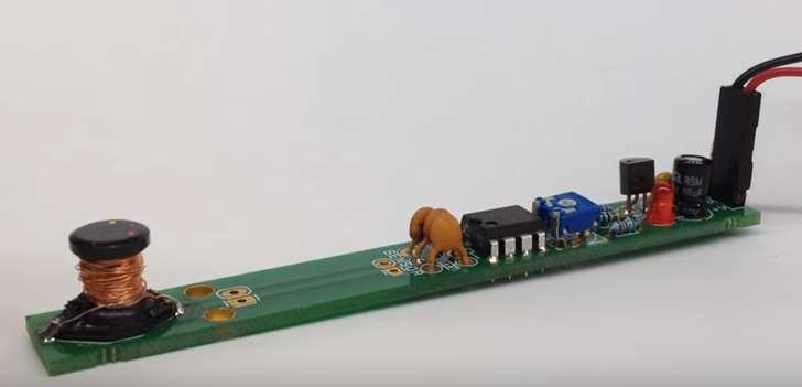
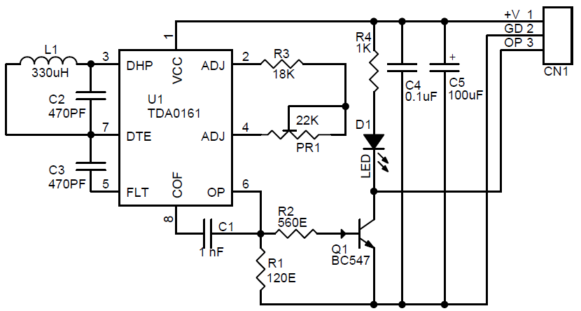
The Metal detector project is designed for metallic body detection by sensing variations in high frequency Eddy current losses. Using an externally-tuned circuit, they act as oscillators. The output signal level is altered by an approaching metallic object. The output signal is determined by supply current changes. Independent of supply voltage, this current is high or low, according to the presence or absence of a closely located metallic object Between pins 3 and 7, the integrated circuit acts like a negative resistor with a value equal to that of the external resistor R3 and trimmer potentiometer PR1 (connected between pins 2 and 4). The oscillation stops when the tuned circuit loss resistance (Rp) becomes smaller than R3. As a result, ICC(close) = 10mA (pins 1 and 6). The oscillation is sustained when Rp is higher than R3, and ICC(remote) = 1mA (pins 1 and 6). Eddy currents induced by coil L1 in a metallic body determine the value of Rp.
- Supply 5-12V DC
- Output Normally High , Provide Low output in presence of Metal
- LED Sensor Active Indicator
- Sensing Distance 5-15mm
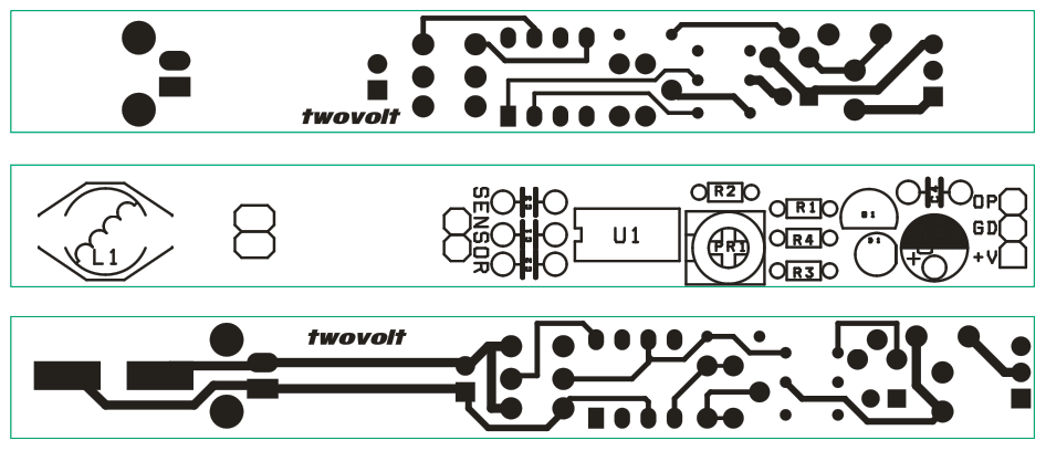
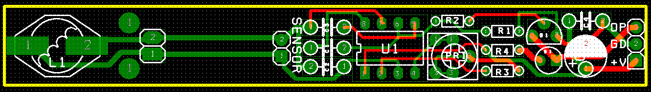
Download PDF Schematic & PCB Layout