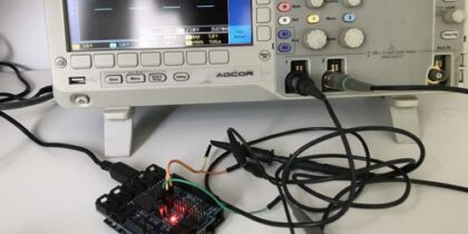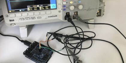
Arduino PWM Generator with duty cycle display
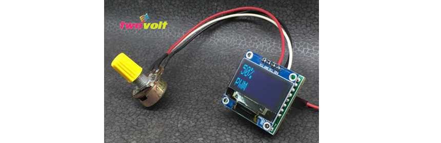
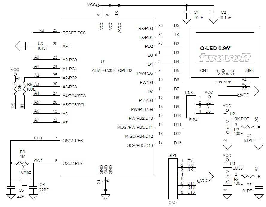
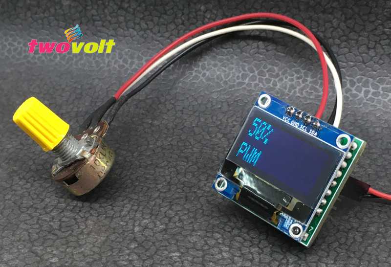
I wanted a PWM signal output from Arduino with PWM duty cycle display………. so here is my project, which generate PWM signal with display, PWM adjustable duty cycle 0-100% and frequency 970Hz output on D5 pin of Arduino. I have tested this project on OLEDuino board. This tiny board has ATmega328 chip and connector for Arduino programming and boot-loader burning. Potentiometer connected to A0 analog port, digital pin D5 provides PWM output. Operating voltage of this circuit is 5V DC. This PWM signal has several uses like dimming an LED, DC Motor Speed control, solenoid driver, generation audio signals, providing analog voltage output with help of RC filter on output of Arduino PWM pin.
- Download Arduino Code
- Download PDF Schematic
- Secrets of Arduino PWM
- Video of this Project
- Arduino PWM Tutorial
- OLED Display Library
- OLED Display Information
Pulse Width Modulation, or PWM, is a technique for getting analog results with digital means. Digital control is used to create a square wave, a signal switched between on and off. This on-off pattern can simulate voltages in between full on (5 Volts) and off (0 Volts) by changing the portion of the time the signal spends on versus the time that the signal spends off. The duration of “on time” is called the pulse width. To get varying analog values, you change, or modulate, that pulse width.