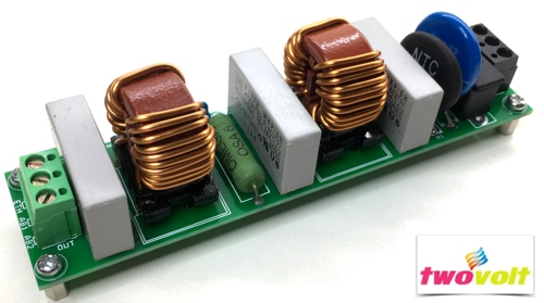
EMI filter circuit using common mode inductors and capacitors

Circuit published here is a dual stage EMI filter. EMI Filters are widely used in applications such as Appliances, Military systems, Aerospace systems , SMPS, VFD drives, AC Servo drives, Energy Management Systems, Computers, Factory Automation Equipment, Industrial Equipment, Medical Equipment, Automotive Battery Charger.
The EMI circuit normally consists of passive components, including capacitors and common mode inductors, connected together to form LC circuits.
The common mode inductor(s) allow DC or low frequency currents to pass through, while blocking the harmful unwanted high frequency currents. The capacitors provide a low impedance path to divert the high frequency noise away from the input of the filter, either back into the device, or into the ground connection. In addition to assisting to meet EMI regulations, the filter also has to meet safety standards.
The inductor temperature rise is measured and for mains operation, the minimum electrical spacing between line, neutral and ground are controlled. This reduces the risk of fire and electrical shock.
Note : Project has been design for multipupose, few components can be omited or mount as per application requirmnet, R1 NTC, R3 MOV, R2 resistors are optional. Value of inductors and capacitors can be selected as per power requirment.
- CN1 AC 100V to 250V AC Input Single Phase
- Maximum Load current up to 10Amps
- CN2 AC Output
Components
- Capacitor C4, C5, C6, C7 : 1K PF 1KV ( 1000V)
- Capacitor C1, C2, C3 : 0.47uF 270V AC X2
- R1 NTC : 10D-20 ( 20MM NTC) for Inrush Current Protection ( Link)
- Common Mode Inductor ( Choke) : T1, T2 : 1MH 10Amps Wurth Part No 744824101
- R3 Metal Oxide Veristor Optional
- F1 Fuse holder and Glass fuse 10Amps
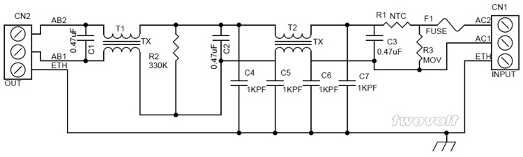
Across-the-line capacitors C1, C2, C3 (X-capacitor) Suppresses differential mode noise
Line bypass capacitors C4, C5, C6, C7 (Y-capacitor) Suppresses common mode noise
Common mode choke coil T1, T2 Suppresses common mode noise
R3 MOV Optional Can be selected as per application requirement
R2 Optional Not Used
R1 NTC to protect inrush current ( Optional Can be directly short using jumper wire)
What is the common mode inductor?
Common mode chokes are specialized inductors designed specifically for common mode EMI filters? The common mode choke consists of two identical windings wound such that the magnetic fields caused by differential mode currents cancel. EMI filter is essential elements.
What is a Common Mode working
A common mode choke is an electrical filter that blocks high frequency noise common to two or more data or power lines while allowing the desired DC or low-frequency signal to pass. Common mode (CM) noise current is typically radiated from sources such as unwanted radio signals, unshielded electronics, inverters and motors. Left unfiltered, this noise presents interference problems in electronics and electrical circuits.

How do Common Mode Chokes Work? (Link)
In normal or differential mode (single choke), current travels on one line in one direction from the source to the load, and in the opposite direction on the return line that completes the circuit. In common mode, the noise current travels on both lines in the same direction.
Common mode chokes have the two or more windings arranged such that the common mode current creates a magnetic field that opposes any increase in common mode current. This is similar to how single line (differential) inductors function. Inductors create magnetic fields that oppose changes in current.
In common mode, the current in a group of lines travels in the same direction so the combined magnetic flux adds to create an opposing field to block the noise, as illustrated by the red and green arrows in the toroid core shown in Figure 1. In differential mode, the current travels in opposite directions and the flux subtracts or cancels out so that the field does not oppose the normal mode signal.
How do I Choose a Common Mode Choke?
The main criteria for selecting a common mode choke are:
Required impedance: How much attenuation of noise is needed?
Required frequency range: Over what frequency bandwidth is the noise?
Required current-handling: How much differential mode current must it handle?
Read More at CoilCraft
EMI/EMC Information
EMC/EMI Filter Design Application Note Download ( schaffner )
Texas Intruments Application
Biricha Application
EMC and Noise Regulation TDK Application
What is EMI Electromagnetic interference?
A broad term covering a wide range of electrical disturbances, natural and man-made, from dc to GHz frequencies and beyond. Sources of disturbance may include radar transmitters, motors, computer clocks, lightning, electrostatic discharge and many other phenomena.
What is EMC Electromagnetic compatibility?
A situation wherein two pieces of electrical or electronic equipment are able to function in the same environment without adversely affecting, or being affected by, each other.
EMI Electromagnetic interference.
A broad term covering a wide range of electrical disturbances, natural and man-made, from dc to GHz frequencies and beyond. Sources of disturbance may include radar transmitters, motors, computer clocks, lightning, electrostatic discharge and many other phenomena.