16X2 LCD Module PCB Layout & Schematic
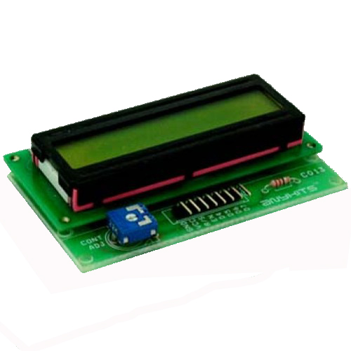
- LCD Module project offers an easy way of interfacing a 16X2 Alphanumeric LCD.
- Interfacing 16X2 backlight alphanumeric LCD in 4 bit mode
- Onboard resistor to limit current to backlight LED
- Preset to adjust the contrast level of the LCD
- 8 Pin Berg connector for easy connection of all pins to the microcontroller board
- PCB dimensions 80 mm x 49 mm

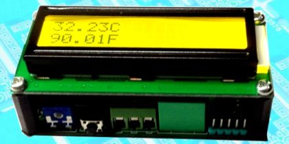
This Project PCB will help you connect a standard 16×2 backlight Alphanumeric LCD to any of your microcontroller project in the 4 bit mode.
Many of micro-controller project use this PCB for display purpose.
PR1 Preset will adjust the contrast setting of the LCD
R1 Resistor will help regulate current flow through the backlight LED
CN1 Connector is a 8 pin connector by which the LCD Display PCB would be connected to your project
A header connector is used to solder the LCD display to the Main PCB. Please remember to solder the jumpers first and then other components on the PCB.
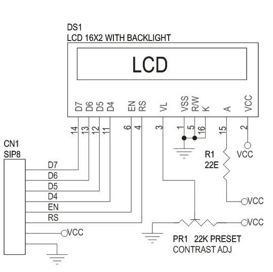
16X2 LCD MODULE WITH HEADER CONNECTOR CIRCUIT
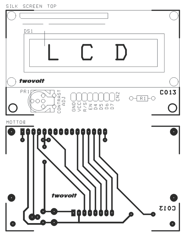
16X2 LCD MODULE WITH HEADER CONNECTOR PCB LAYOUT