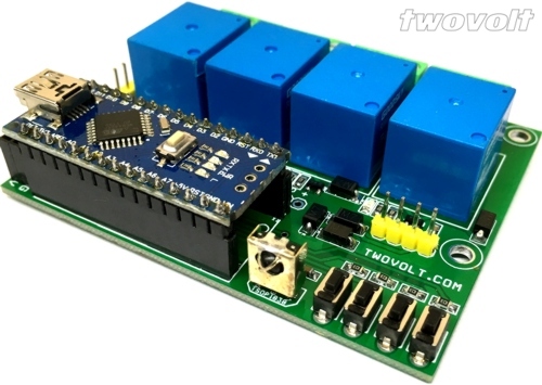
Arduino 4 channel on-off (toggle) switch

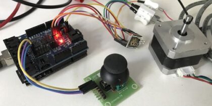
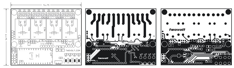
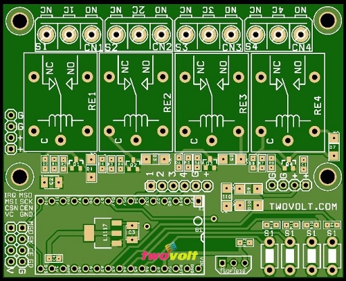
Arduino based 4 channel toggle switch using 4 relays, 4 tactile switches, an Arduino Nano, the circuit required 12V DC, the relay can handle load up to 7Amps 230V DC or 7Amps/30V DC.

ARDUINO CODE
//Buttons
int SWITCH1 = A3;
int SWITCH2 = A4;
int SWITCH3 = A5;
int SWITCH4 = 7;
//Relays
int RELAY1 = 5;
int RELAY2 = 4;
int RELAY3 = 3;
int RELAY4 = 2;
//States for RELAY-1 and SWITCH-1
int state1 = HIGH; // the current state of the output pin
int reading1; // the current reading from the input pin
int previous1 = LOW; // the previous reading from the input pin
//States for RELAY-2 and SWITCH-2
int state2 = HIGH; // the current state of the output pin
int reading2; // the current reading from the input pin
int previous2 = LOW; // the previous reading from the input pin
//States for RELAY-3 and SWITCH-3
int state3 = HIGH; // the current state of the output pin
int reading3; // the current reading from the input pin
int previous3 = LOW; // the previous reading from the input pin
//States for RELAY-4 and SWITCH-4
int state4 = HIGH; // the current state of the output pin
int reading4; // the current reading from the input pin
int previous4 = LOW; // the previous reading from the input pin
// the follow variables are long’s because the time, measured in miliseconds,
// will quickly become a bigger number than can be stored in an int.
long time1 = 0; // the last time the output pin was toggled
long time2 = 0;
long time3 = 0;
long time4 = 0;
long debounce1 = 200; // the debounce time, increase if the output flickers
long debounce2 = 200;
long debounce3 = 200;
long debounce4 = 200;
void setup()
{
pinMode(SWITCH1, INPUT);
pinMode(SWITCH2, INPUT);
pinMode(SWITCH3, INPUT);
pinMode(SWITCH4, INPUT);
pinMode(RELAY1, OUTPUT);
pinMode(RELAY2, OUTPUT);
pinMode(RELAY3, OUTPUT);
pinMode(RELAY4, OUTPUT);
}
void loop() {
reading1 = digitalRead(SWITCH1);
reading2 = digitalRead(SWITCH2);
reading3 = digitalRead(SWITCH3);
reading4 = digitalRead(SWITCH4);
// if the input just went from LOW and HIGH and we’ve waited long enough
// to ignore any noise on the circuit, toggle the output pin and remember
// the time
//Condition Relay 1
if (reading1 == HIGH && previous1 == LOW && millis() – time1 > debounce1) {
if (state1 == HIGH)
state1 = LOW;
else
state1 = HIGH;
time1 = millis();
}
//Condition Relay 2
if (reading2 == HIGH && previous2 == LOW && millis() – time2 > debounce2) {
if (state2 == HIGH)
state2 = LOW;
else
state2 = HIGH;
time2 = millis();
}
//Condition Relay 3
if (reading3 == HIGH && previous3 == LOW && millis() – time3 > debounce3) {
if (state3 == HIGH)
state3 = LOW;
else
state3 = HIGH;
time3 = millis();
}
//Condition Relay 4
if (reading4 == HIGH && previous4 == LOW && millis() – time4 > debounce4) {
if (state4 == HIGH)
state4 = LOW;
else
state4 = HIGH;
time4 = millis();
}
digitalWrite(RELAY1, state1);
digitalWrite(RELAY2, state2);
digitalWrite(RELAY3, state3);
digitalWrite(RELAY4, state4);
previous1 = reading1;
previous2 = reading2;
previous3 = reading3;
previous4 = reading4;
}