900W PFC Circuit
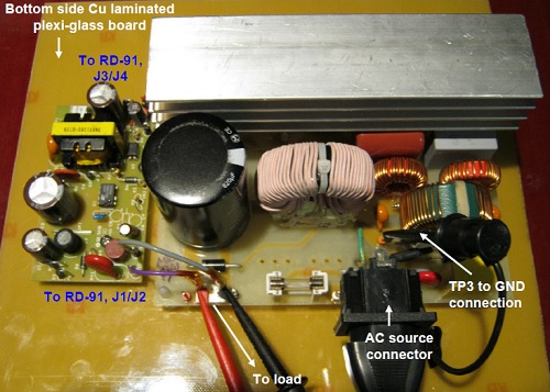
This PFC circuit is designed using Power Integration’s HiperPFS PFS729EG integrated PFC controller. This design is rated for a continuous output power of 900 W and provides a regulated output voltage of 380 VDC nominal maintaining a high input power factor and overall efficiency from light load to full load.
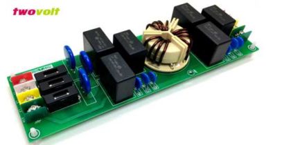
4.1 Input EMI Filtering and Rectifier
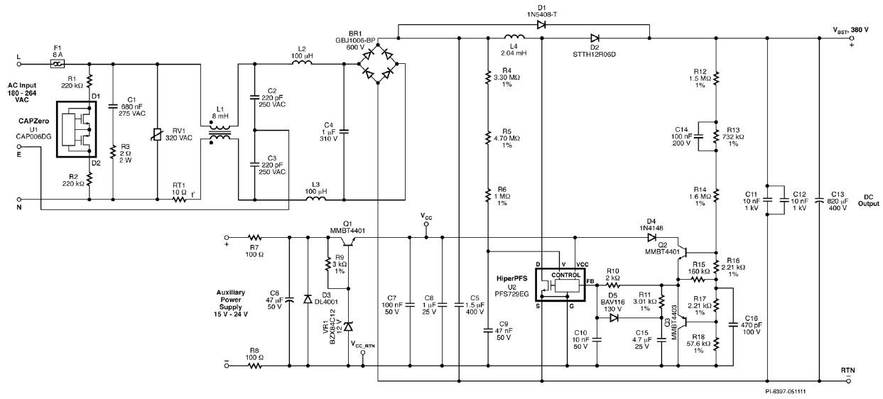
Fuse F1 provides protection to the circuit and isolates it from the AC supply in case of a fault. Diode bridge BR1 rectifies the AC input. Capacitors C1, C2, C3, and C4 together with inductors L1, L2 and L3 form the EMI filter reducing the common mode and differential mode noise. Resistors R1, R2 and CAPZero, IC U1 are required to discharge the EMI filter capacitors once the circuit is disconnected. High frequency decoupling capacitor C5 after the bridge reduces the loop area of the high frequency loop and helps reduce the noise coupled into the input wires. Resistor R3 connected in series with capacitor C1 provides damping. Metal Oxide Varistor RV1 is placed across AC power lines to provide differential mode surge protection.
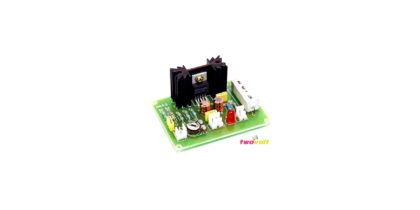
4.2 PFS729EG Boost Converter
The boost converter stage consists of inductor L4, diode rectifier D2 and the PFS729EG IC U2. This converter stage works as a variable frequency continuous conduction mode boost converter and controls the input current of the power supply while simultaneously regulating the output DC voltage. Diode D1 prevents a resonant buildup of output voltage at start-up by bypassing inductor L4 while simultaneously charging output capacitor C13. Thermistor RT1 limits the inrush current of the circuit at start-up. In higher performance (efficiency) power supplies, this thermistor is shorted after start-up using a relay. Efficiency measurements should therefore be taken with RT1 shorted to obtain maximumefficiency data. Capacitors C11 and C12 are used for reducing the loop length and area of the output circuit to reduce EMI and overshoot of the voltage across the drain and source of the MOSFET inside U2 at each switching instant.
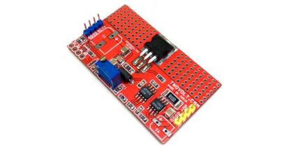
4.3 Bias Supply Regulator
The PFS729EG IC requires a regulated supply of 12 V for operation. Should this supply exceed 13.4 V, the IC could be damaged. Resistors R7, R8, R9, Zener diode VR1, and transistor Q1 form a shunt regulator that prevents the supply voltage to IC U2 from exceeding 12 V. Capacitors C6, C7 and C8 filter the supply voltage to ensure reliable operation of IC U2. Diode D3 protects the circuit against accidental reversal of polarity of the bias supply.
4.4 Input Feed Forward Sense Circuit
The input voltage of the power supply is sensed by the IC U2 using resistors R4, R5 and R6. The capacitor C9 filters any noise on this signal.
Circuit From www.powerint.com